Fault refers to a state or some components in the dynamic system function of equipment can not complete the required function under specified conditions of the failure caused the performance of the whole system can not meet the specified requirements, and do not want to or bad situations or events' when system failure occurs, the variables in the system or part of them show different characteristics and normal state. This difference includes rich fault information. How to collect and identify the characteristics of fault information, and use it to detect faults and subsequent fault isolation is the task of fault diagnosis.
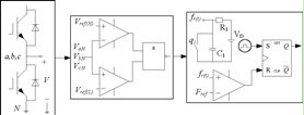
According to the introduction, a phase bridge arm, a switch device open circuit or a phase bridge arm two switch device open circuit fault diagnosis, and a fault diagnosis method based on direct measurement of signal without a model voltage detection method is a detection method of measurable signal. The mode of how to run under the open fault of the inverter drive bridge arm is analyzed, and the lower pipe voltage is taken under the normal state. The first measurement of tube voltage, using the voltage comparator and the threshold level and compared with each other, measurement noise cancelling depends on the selection of threshold, output again after low-pass filter, to eliminate the dead zone and switch power tube has the adverse effect of the delay switch, we want to get accurate results, and latched by the trigger icon.
Figure 1: diagnostic scheme
Whether the fault occurs or not depends on measuring the line voltage difference between the output of the inverter and the line voltage at normal time. The current mode of fault diagnosis takes at least one fundamental period, while the voltage mode only needs 1/4 fundamental periods, and the diagnosis time can be greatly reduced.
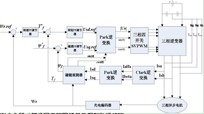
Figure 2: fault tolerant vector control system structure for rotor field orientation
Time and space vector modulation technology (SVPWM) will be the first voltage vector three-phase coordinate system on a-y to coordinate changes, and then follow the four switch inverter in normal working condition switch mode chart to draw a hexagon, including two, six amplitude zero vector values are the same but different vector hexagonal phase.
Figure 3: positive hexagon voltage vector
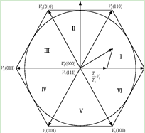
The hexagon is divided into six sectors by six non zero voltage vectors, and there is a zero vector. In order to make the corresponding rotating magnetic field approaching the circle, we let the eight voltage vectors be linearly combined and set the zero vector to the original point. Usually, the voltage space vector modulation technology can be roughly divided into three parts, including three phase voltage vector sector assignment, voltage vector synthesis combination form and PWM generation control algorithm. The reference voltage space vector sector assignment determines the combination form of voltage vectors and the generated PWM. The different combinations of vectors will directly affect the harmonic components and switching losses. Through the analysis of the production and working principle of SVPWM, the Dongguan motor factory first determines which sector is the reference voltage space vector. Then, according to the voltage vector in different sectors, we take different combinations of the two voltage basic vectors and zero vectors in the sector to generate the required reference voltage vectors, and finally generate PWM. Then the modulation design of the space voltage vector under the fault-tolerant control condition is carried out.
Figure 4: inverter fault-tolerant topology
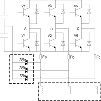
The four switching inverter can produce four kinds of voltage vectors and the amplitude is not exactly the same, but the zero voltage vector can not be produced. Therefore, at the time of modulation, the required zero vector can only pass through two phase difference of 180 in one period.